How to design a push pull converter – basic theory, construction, and Push pull transformers – inductors & transformers Uc3843 smps circuit diagram
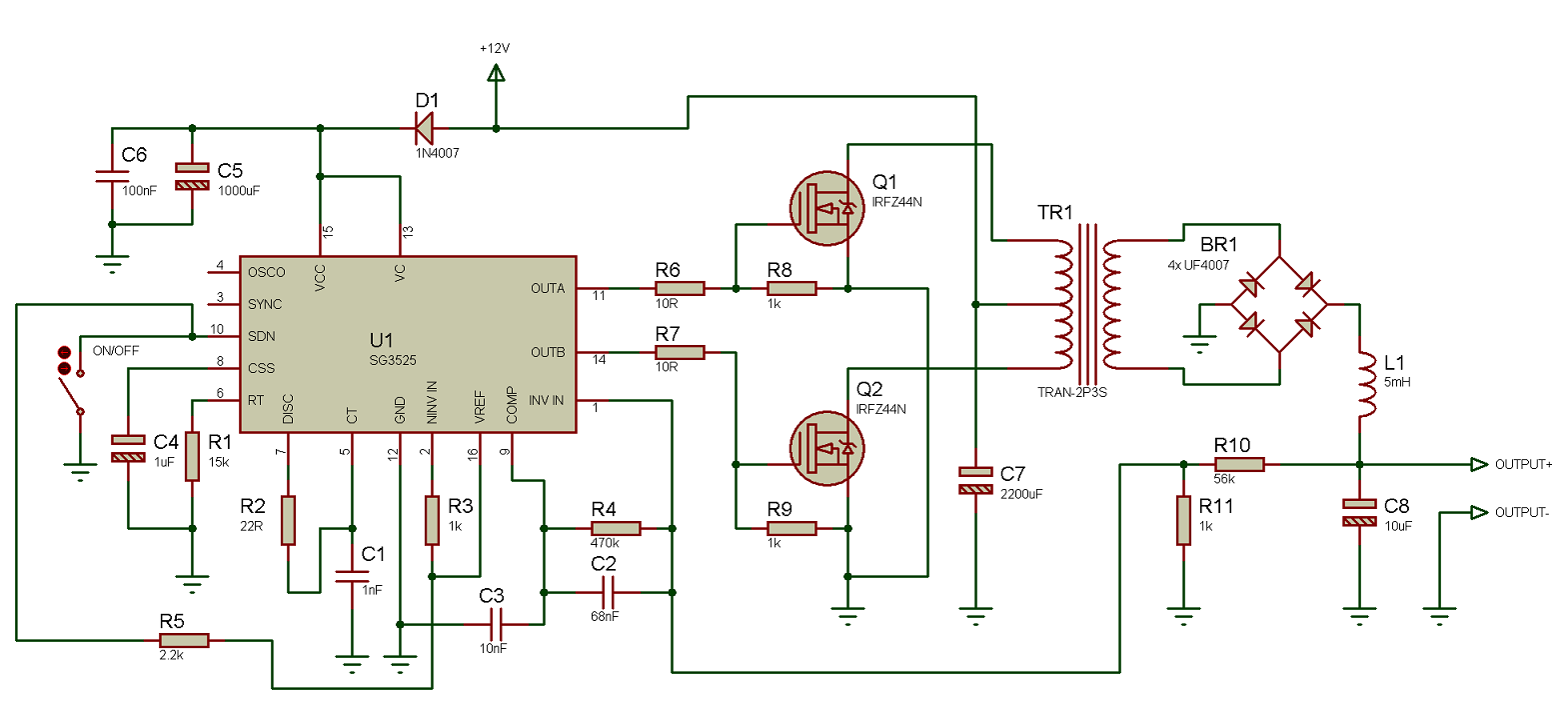
Sg3525 Pnverter Circuit Diagram
Class ab push pull amplifier circuit diagram Circuit smps push pull generated converter bridge half tahmid click enlarge Pull push converter smps diagram isolated diodes parallel eevblog forum
Tl494 adjustable switching power supply (universal buck boost converter
Switch mode power supplySmps circuit Push operational fig16 syed azizPush pull dc to dc converter complete circuit diagram power supply.
Smps circuit: everything you need to knowPush pull smps circuit diagram Smps circuit schematic explanation switched psu 12v switching circuits subwoofer figDiodes in parallel.

Smps power supply diagram block linear between dc mode voltage ac wikipedia circuit does converter computer when work switched push
(when) does an smps use a push-pull converter to translate the voltageSmps topomagic Push pull converter application notesPush pull converter converters smps power.
Push pull amplifier circuit, operation, advantages and disadvantagesPush pull power supply diagram Push pull smps converter हिन्दी ! learn and grow !Using the sg3525 pwm controller.
Push pull converter smps output filter dc supply power voltage translate does use when switch mode lc needed shows which
Sg3525 pnverter circuit diagramHow to design an isolated, high frequency, push-pull dc/dc converter Mosfet power amplifier diagramElectrical schematic of push-pull converter..
Mosfet amplifier power diagram push pull circuit amplifiersPush pull converter smps Smps switched psu supply regulatorPush pull transformer high switching voltage smps circuit isolated open cet technology schematic source output.

Push-pull switched mode power supply
Push circuitdigest tda2030 subwoofer ampli circuits amplifiersSmps 2 x 50v 350w circuit for audio power amplifiers Smps circuit: everything you need to knowSmps 50v amplifier 350w amplifiers switching 100w schematics.
Ross wiring: online wiring diagram maker converter circuit cityCircuit diagram notes converters typical Switch mode power supplySwitch mode power supplies..

Schematic diagram of a push-pull operational amplifier.
Push advantages disadvantages explanationPush-pull switched mode power supply Push pull smps circuit diagram with explanationBoost smps push pull superago.
Smps topomagicKnow all about smps (switch mode power supply) Circuit sg3525 diagram push pull pwm controller schematic using frequency induction transformer inverter core pulse stack converter explanation power circuits.


How to Design an Isolated, High Frequency, Push-Pull DC/DC Converter

SMPS 2 x 50V 350W Circuit for Audio Power Amplifiers - Homemade Circuit

PUSH PULL SMPS CONVERTER हिन्दी ! LEARN AND GROW ! - YouTube

Class Ab Push Pull Amplifier Circuit Diagram

Push Pull Converter Application Notes | MPS Industries, Inc.

transformer - High open-circuit voltage in isolated push-pull SMPS

Mosfet Power Amplifier Diagram | Home Wiring Diagram
