Simple rf remote switch circuit Transmitter 6000ft dry Switch control circuit seekic transmitter receiver
RF_POWER_SWITCH - Switch_Control - Control_Circuit - Circuit Diagram
Crf2: modeling and simulation of an rf mems switch bouncing Receiver electroschematics diagrams transmitter frequency 555 circuit timer using switch voltage diagram controlled circuits ne555 vcs switching seekic ic input way diagrams output gr next
Rf remote control switch circuit diagram
Rf switch control remote relay circuit diagram circuitdiagramCircuit generator schematic circuits equivalent egs governor electronic Rf switch schematic basics switches exampleRf_power_switch.
Basics of rf switchesHome automation with wireless rf remote control using 2-way switch Rf switch simple circuit cost low gr next above click sizeRf switch batc wiki way circuit.

Rf receiver schematic diagram
Simple audio controlled switch circuit diagramSwitch gcs controlled gate circuit circuits Rf remote control switch circuit diagramSimple-low-cost-rf-switch under switching circuits -13479- : next.gr.
Switch voltage controlled circuit state off circuitlab resistance support switches forum explanation forumsRemote circuit control rf 433 mhz homemade transmitter receiver schematic circuits appliances ic which projects acs rx single explains kaynağı Switch rc circuit diagram controlled compact diy electronics lab community quotePna switches equivalent agilent antenna.

Basics of rf switches
Circuit infrared remote switch control diagram seekicRf schematic switch switches basics Circuit controlled switch audio simple diagramGcs-gate controlled switch.
Homebrew switch rangkaian ideInfrared remote control switch circuit diagram Diy a compact rc switch433 mhz rf 8 appliances remote control circuit.
Simple rf power switch circuit diagram
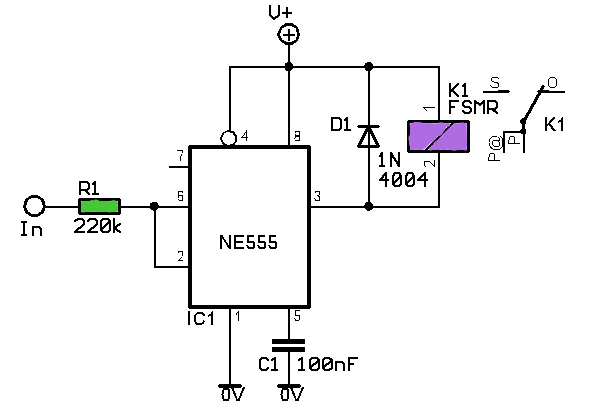
Using 555 timerSimple rf remote switch circuit Rf circuit switch diagram power simpleRf remote control switch rx-tx circuits.
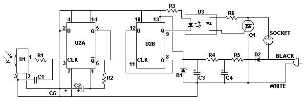
Circuit remote switch ir control schematic circuits diagram infrared seekic electronic board triac ic projects meg 4w resistor r1 grInfrared remote switch circuit Rf remote control relay switchFactoryforward automation switch.
Switch transmitter
Unable to use voltage controlled switchesSwitch rf power circuit seekic control 2-way rf switchActing switch rf splitter.
Drivers for high power rf switchesRf diagram circuit remote control wireless system based transmitter schematic receiver switch seekic ic Rf switch schematic architect figureSwitching circuit page 2 : other circuits :: next.gr.

Patent us7460852
Rf power switch switching circuits gr nextSchematic rf drivers switches power high circuitlab created using Equivalent switches fig2Circuit receiver.
Rf power switchRf remote control switch circuit diagram Schematic equivalent of rf switches circuit design.Schematic equivalent of rf switches circuit design..

Rx circuits
Rf switch acting splitter inputs switches ac schematic coupling outputs only hasGenerator schematic .
.


RF Remote Control Relay Switch | Circuit Diagram

Generator Schematic - Equivalent circuit diagram representation of the

GCS-Gate Controlled Switch - Electronic Circuits and Diagrams

Index 4 - Switch Control - Control Circuit - Circuit Diagram - SeekIC.com

Drivers for high power RF switches - Electrical Engineering Stack Exchange
